Wall Clock Made with AVR MCU and LED Display
Idea
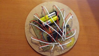
The goal of this project was to explore using a numeric LED display with a microcontroller (MCU). To make it more engaging, I decided to create a wall clock that displays time both digitally and analogically. I chose the Atmega16L MCU for its 26 I/O pins—12 for the numeric display, 12 for the 2mm LEDs, and 2 for the buttons. The clock features two buttons: one to add hours and another to add minutes. The 2mm LEDs around the edge represent seconds, while the numeric display in the center shows hours and minutes.
Display
I sourced my display from eBay without a datasheet, but the pin configuration is typically similar across different displays. The four 7-segment digits are controlled by 12 I/O pins—each digit consists of 8 segments (7 for numbers and 1 for the dot). The remaining four pins are used as grounds for each digit. To illuminate all four digits, the MCU must rapidly switch between them.
Timers
Timers are fundamental counters in microcontrollers. The ATmega16 features two 8-bit timers and one 16-bit timer. An 8-bit timer (using 8 registers) can count up to 255 (2^8), while the 16-bit timer (using 16 registers) can count up to 65,536 (2^16). Once a timer reaches its maximum value, it overflows and starts counting from zero again.
For this project, the MCU operates at a 1 MHz frequency, equating to 1,000,000 ticks per second. Since the counters can only handle values up to 255 or 65,536, they will overflow once these limits are reached. To configure the timer properly, you need to set the prescaler and mode bits accordingly. Detailed configuration information is available in the MCU’s datasheet.
I used the 16-bit timer in CTC (Clear Timer on Compare) mode. In this mode, the timer resets to zero when it reaches a predefined value, with an external interrupt handling the timing. The main thread handles logic and redrawing, while the interrupt handles the time counting. For further details, you can refer to tutorials on AVR timers and AVR timer calculators.
Result
Using the internal timer for precise timekeeping is not ideal, as the error margin can be significant, leading to a loss of accuracy over time. To improve accuracy, an external timer, such as a Crystal Oscillator, is recommended.
Update
I decided to upgrade the project by incorporating an external DS1307 RTC (Real Time Clock) module. I found a suitable RTC library, removed the manual buttons, and integrated the RTC for more accurate timekeeping.
You can find the source code here: https://github.com/mbodis/wall_clock
 |
 |
 |


Comments
Post a Comment