Robotic Arm with Computer Vision
Robotic Arm with Computer Vision - Picking Up the Object
 |
Idea
Environment
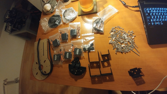
The setup consists of several components assembled together. I used an old table as the base, repainting it white to provide better contrast with the objects. The robotic arm, which I purchased from eBay, is mounted on the middle of the longer side of the table. The arm has six servo motors, including a rotating base and claws at the other end. The parts are made of aluminum and are quite sturdy.
Next, I cut and mounted perforated metal ledges to the corners of the table, securing everything together. I then attached an RGB LED strip to the bottom side of the top part of the structure. Finally, I placed a USB camera at the top of the setup to capture the entire scene.


Communication with Arm
Logic flow
- The input from the camera runs in a separate thread, where it preprocesses the "interesting frame" (the frame detected after movement). The result of this preprocessing is a list of detected objects with their coordinates.
- The interesting frame is then sent to the main logic module. Here, all the other modules are registered. If no module is active, the system tries to initialize the first module that satisfies the initial conditions. If a module is already active, the interesting frame is sent to that module. The module handles the logic and decides what to do next. It then sends movement commands to a queue for the USB communicator.
- The USB communicator repeatedly reads messages from the queue and sends commands to the controller via USB. The controller then moves the servo motors accordingly.
 |
| schema of logic flow |
Calculation of the Next Move
- The first part involves base rotation (imagine viewing the arm from above). This is a trigonometry exercise where we know all the points of a triangle and two sides, and we need to calculate the angle. We then convert this angle to milliseconds for the servo controller.
- The second part involves rotating three servos to tilt the arm (imagine viewing the arm from the side). In the initial version, the height of the object is unknown, so we use a constant. This problem is similar to the previous trigonometry problem, but here we have one side and angle for each segment. By substituting the right values, we can determine if the arm has reached the object. I used brute force to calculate the three angles, and the process took less than a second.

Modules
The goal is to create an application with easily insertable modules. Each module can be thought of as a series of moves with custom logic, extended from a template class. Each module is defined by a list of states. A state can change based on one of the following triggers:
- Time Trigger: Wait for a specific time before executing the next move.
- Interesting Frame Trigger: When movement is detected by the camera.
- Command Execution Trigger: Wait for a signal from the USB controller indicating that the move was executed.
For example, a module for picking up an object could have the following states:
- Start (triggered by an interesting frame)
- Pick up the object (triggered by time)
- Move the object (triggered by time)
- Release the object and return to the default position (triggered by time)
- Verify if the object was moved (triggered by command execution)
First testing
While working with C++ and OpenCV, I encountered a small issue: you cannot display an image from a background thread; only the main thread can call the imshow() method. To solve this, I used a singleton instance to store the images, and the main thread then displays them.
One of the unresolved issues is detecting the object's height. It’s not possible to determine the height from a single camera. This could potentially be addressed by using a sensor at the end of the arm or another approach.
Despite these challenges, the initial tests for picking up objects were successful. However, more calibration is required. After calibration, machine learning could be used to identify the optimal spot on the object for successful picking. Additionally, the claws need to grip the object tightly enough to prevent it from slipping.


Comments
Post a Comment